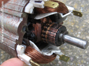
DC Generator?
Without altering its design, an Electric generator can function as a DC motor. Consequently, a DC machine can be commonly referred to as a DC motor or DC generator.
Parts in DC generator
Yoke in DC machine
The term “yoke” refers to a DC machine’s outside frame. Steel or cast iron is used in the construction. It not only gives the entire assembly mechanical properties, but it also needs to carry the magnetic flux generated by the field current.
Shoes for poles
Screws or welding are used to attach the poles to the yoke. They are attached to pole shoes & carry stator winding.
Pole shoes have two functions: First, they stabilize field coils, and second, they evenly distribute flux in the air gap.
Winding a field
Copper is typically used to make them. Each pole has a field coil previously wrapped, positioned there, and linked together in series. When powered, they form alternating the North and South poles because of the way they are wrapped.
The core of the armor
A DC machine’s rotor is indeed the armature core. It has slots to carry the armature winding and is cylindrical in appearance. To minimize eddy current sufferers, the armature is constructed from thin, circular steel discs that have been laminated. It might have air ducts for the radial airflow needed for cooling. The shaft is connected to the magnet.
Read More: Solar Energy Firms – How It Stacks Up to Competition
Winding an armature
Typically, an armature slot holds a formerly wrapped copper coil. The armature conductor is separated from one another and the armature core by an insulation layer. Either the lap winding technique or the wave winding method can be used to wind an armature. In most cases, double-layered lap or wave windings are used. In an armature with a double stack winding, there will be two separate coils in each slot.
Brushes and commutators
Using a commutator-brush setup, the armature winding is connected. In a dc generator, a commutator’s task is to gather the current produced in the armature conductors. In contrast, the commutator in a DC motor aids in supplying current towards the armature wires.
A copper set insulated from one another segments make up a commutator. The quantity of armature coils is the same as the number of segments. The commutator is linked to the shaft, but each segment is wired to an armature coil. Graphite or carbon are typically used to make brushes. As the commutator rotates, they settle on the segments and slide along them, maintaining body contact and collecting or supplying the current.
How do DC generators operate?
The electromagnetic induction laws of Faraday are the basis for a DC generator functions. According to Faraday’s law, an electromotive force is generated in the system’s conductor, which is exposed to the magnetic field. This magnetic field changes continuously as the magnetic changes its position. This phenomenon also happens when the conductor is transported in the magnetic field.
The conductor will produce a current if it is steered along a closed path. According to the right-hand rule of Fleming states that when the conductor’s motion changes, so do the current’s direction.
Working in DC
Consider the situation where the conductor at the left travels upward while the armature is rotating in a clockwise direction. The conductor will move downward as the armature accomplishes its half rotation. The current will flow in alternating directions. A current reversal occurs as the interconnections of the armature conductors are switched around. Thus, the terminals experience direct currents.
It is very simple and easy to understand that when we apply the electromagnetic field, in the coil, the current is produced. The current is called the induced current, and when this coil is placed in the field of magnetic, then current is also produced.
Let’s imagine an armature revolving counterclockwise and a conductor motion changes and it start to travel upward from the left. The conductor will move downward whenever the armature has completed half of its rotation. At this, the armature passes the current and changes its direction. On the other hand, a split ring commutator reverses the interconnections of the armature conductors in response to a current reversal.
Conclusion
In conclusion, the terminal allows the current to move in one direction.
DC generator losses
In a Dc generator, the input power is not entirely converted into the output power. A certain amount of input power is lost in various ways. Losses in a DC machine can be broadly divided into two categories:
Loss of Copper
When the current passes through to the winding, copper is lost. The resistance in the turning is to blame for these losses. Armature loss, field winding loss, and brush strain hardening loss are the three subtypes of copper loss.
Losses of the core or iron
When the armature spins in the magnetic field, there are certain losses in the iron core. Core losses are different kinds of losses than to iron. Hysteresis loss & Electrical resistance loss are two types of losses that these losses fall and cannot be reuse.
What are the DC generator’s three main components?
An electrical device known as a DC generator transforms mechanical energy into electricity. The primary components are the magnetic field system, the armature & commutator, and the brush gear.

